|  |
|||||||||||||||||||||||||||||||||||||||||||||||||||||||||||||||||||||||||||||||||||||||||||||||||||||||||||||||||||||||||||||||||||||||||||||||||||||||||||||||||||||||||||||||
|
Solid beam axles rely largely on the pneumatic properties of the tyres at their ends. This form of suspension has rarely been used in the last fifty years except for the occasional van. Double wishbone suspension is also unsuitable for everyday road use although the precise of movement it allows makes it for race circuit use - e.g. Engine position and transmission layout greatly affect the handling characteristics of a car. The engine block, one of the heaviest components, within the vehicle should not move its centre of gravity too far from the middle of the vehicle - otherwise its balance is affected. Similarly For example, the mid-engine roadster, MR, exploits both its tendancy to oversteer and its optimum centre of gravity creating the highly reactive and nimble handling required of a sports car. Most family cars are configured as FF - front wheel drive. Its tendancy to understeer, in a predicable manner, in an emergency situations is widely perceived as a 'safety feature'. Four wheel drive transmission - 4WD is now regularly exploited by both rally and circuit based cars. Normally neutral steering characteristics can be varied dynamically with the aid of computer assisted power distribution. Eg. Mitsubishi Lancer, Subaru Impreza and Nissan Skyline. In order to propel a car along the road you need to connect the power developed in its engine to its driven wheels. This is done by connecting the crankshaft to a gearbox, with an intervening clutch mechanism, to a final drive differential - which attaches to the axle of the driven wheels. This whole arrangement is collecticely referred to a The clutch is a mechanism that allows the connection of the crankshaft to be temporarily disengaged from the gearbox whilst the driver selects a different gear. For a given engine output (rpm) the eventual vehicle speed is determined by the 'gear ratio' of the ' The ratio of a specific '
Most sports cars use a petrol engine that operates on a the piston reaches the top of the cylinder at the end of this stroke, the exhaust valve closes, the inlet valve opens and the cycle begins again with induction. During the four strokes, the crankshaft rotates twice, but since the valves need to operate only once during each cycle, the camshaft that opens them is driven at half crank speed - rotating once every four strokes. As we have already seen; two valves are needed to control the the four stroke combustion cycle. An inlet valve controls the fuel air mixture and an exhaust valve governs the escape of the spent gases. During the compression and combusion cycles both valves are closed. The exhaust valve is heated by the escaping hot gases. Typically operating at temperatures around 800°C, it is made from a heat resistant steel alloy. Because the inlet valve is cooled by the incoming mixture it runs much cooler. The arrangement of valves and cams is varied, but the major designs are shown here. As the camshaft rotates the lobes of the cams depress the poppet valves, opening them and compressing their valve springs. As the cam profiles smooth out the springs expand re-closing the valves. The most efficient, and hence powerful engines use multiple inlet and exhaust valves. This arrangement allows the central location of the spark plug. Combustion spreads evenly throughout the combustion chamber (at the top of cylinder). This allows designers to increase the compression ratio - which means more horsepower. By altering the profile of the cam, usually flattening the tip, the duration of the valve's open state can be increased - allowing more gas to escape or to be introduced into the cylinder. As part of the induction cycle a mixture of fuel and air is introduced into the combustion chamber. As the piston descends in the cylinder, creating a vacuum, air is drawn (via an air filter) from the atmosphere through the carburettor where fuel is added, in liquid form, via a The power that an engine develops depends on how much energy is released during each power cycle. This is directly related to how much petrol is mixed into the fuel air mixture created by the carburettor. Theoretically the more this is compressed the greater the amount of energy will be released. The compress- ion ratio is the amount by which the original volume is reduced by the piston during the compression cycle. Very high ratios (greater than 8:1) usually result in uneven detonation, with loss of power, due to the distance of the mixture from the spark. This is referred to as 'pinking' or 'knocking'. When the bore size of a cyclinder approaches that of the piston stroke length - this is referred to as ' As we have already seen. The more fuel you can ignite within a given period of time the more power an engine will develop. Several strategies exist for achieving this ! The first is obvious - add more cylinders, bigger ones ... or both. This approach is typified by the ' The process of turbocharging uses an entirely different technology to achieve both increased compression and greater engine throughput. Turbocharging is a type of more air into the cylinders; then just add more fuel and you've got more power - simple !. Turbochargers are constructed from two linked sections; a turbine that drives a centrifugal pump via a linked shaft. Exhaust gases, straight from the manifold, are directed across the blades of a turbine which causes the impellor to draw and compress ambient air - driving it toward the inlets of the engine. Provided that the fuel injection system or carburettor can continue to deliver increasing amounts of fuel to match the increasing airflow, an increasing amount of power will be developed. The Laws Of Thermodynamics dictate that 'energy cannot be created or destroyed'. So when a gas is compressed the molecules collide more often - raising its overall temperature. This side effect results in poorer combustion, however, it can easily be addressed by passing the air through an |
||||||||||||||||||||||||||||||||||||||||||||||||||||||||||||||||||||||||||||||||||||||||||||||||||||||||||||||||||||||||||||||||||||||||||||||||||||||||||||||||||||||||||||||||
|
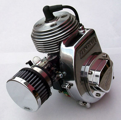
Liquimatic Torque Convertor Sport, Bigfoot, Liquimatic, Go Quad Pre 1995 Go-peds Geo Sport, Geo Bigfoot, Geo X, S-25 GSR 40, GSR 40 TSI |
||||||||||||||||||||||||||||||||||||||||||||||||||||||||||||||||||||||||||||||||||||||||||||||||||||||||||||||||||||||||||||||||||||||||||||||||||||||||||||||||||||||||||||||||
 |
||||||||||||||||||||||||||||||||||||||||||||||||||||||||||||||||||||||||||||||||||||||||||||||||||||||||||||||||||||||||||||||||||||||||||||||||||||||||||||||||||||||||||||||||
|
|
||||||||||||||||||||||||||||||||||||||||||||||||||||||||||||||||||||||||||||||||||||||||||||||||||||||||||||||||||||||||||||||||||||||||||||||||||||||||||||||||||||||||||||||||


 The profile of an aerofoil accelerates air flowing over its upper surface compared with that of the lower producing a lower pressure on the upper surface. Taken together, and acting against gravity, the effect is known as lift.


 Super X, Super Bigfoot, Super Go Quad


